[ Team LiB ] Previous Section Next Section

Student Exercises

1:

Consider the ratio control strategy shown in Figure 12-1b. If the blend stream has a concentration measurement and controller, construct the control instrumentation diagram where the output of the concentration controller is the desired ratio of stream B to stream A flows.

2:

Consider the high-temperature select control problem shown in Figure 12-2. Modify the control instrumentation diagram to include a cascade-control strategy, where the output of the reactor temperature controller is the setpoint to a reactor inlet temperature controller. The reactor inlet temperature controller then manipulates the flow to the preheat exchanger.

3:

Consider a gas-phase reactor where a valve on the output stream is normally regulated to maintain a desired outlet composition. Design a selector-based control strategy that switches to pressure control if the pressure is too high.

4:

Consider a waste treatment system. A pH controller may need to adjust the pH by manipulating either basic or acidic stream flow rates. Design a split-range control strategy to do this.

5:

Consider Example 12.1, where input 1 is the cold glycol make-up flow rate, and input 2 is the hot glycol make-up flow rate. The steady-state temperature is 20°C, which is also the vessel feed temperature. At steady-state the cold and hot glycol make-up flow rates are 0. The parameter values are


fov     =  1/30; % minutes^-1
ua      =  24  ; % kcal/min deg C
vrhocp  = 850  ; % kcal/deg C
vrhocpj = 250  ; % kcal/deg C
Tjfcold = -20  ; % deg C
Tjfhot  = 100  ; % deg C
Tjs     =  20  ; % deg C
vj      = 250  ; % liters

and the state space model matrices are
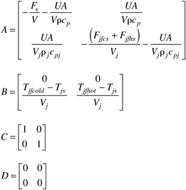
graphics/12equ08.gif


Solve for the numerical values of all matrices. Design a jacket temperature controller and implement the SIMULINK diagram shown in Figure 12-7. Discuss your jacket temperature controller design and tuning procedure. Notice that the jacket temperature output has a range of 100%, constrained between –50% and +50%. The cold valve is fully open at –50% and fully closed at 0%. The hot valve is fully closed at 0% and fully open at +50%,

6:

Develop a SIMULINK diagram of a cascade control strategy, where Figure 12-7 represents the inner-loop (jacket temperature) control system. The output of the primary (outer-loop) controller that you develop should be the setpoint for the jacket temperature controller. Discuss the design and implementation (tuning) of both controllers. Use the parameter values from Exercise 5.


    [ Team LiB ] Previous Section Next Section