9.2 The Equivalent Feedback Form to IMC
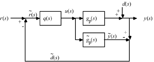
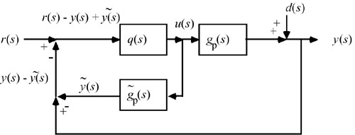
In this section we derive the standard feedback equivalence to IMC by using block- diagram manipulation. Begin with the IMC structure shown in Figure 9-1; the point of comparison between the model and process output can be moved as shown in Figure 9-2.


Figure 9-2 can be rearranged to the form of Figure 9-3.

The arrangement shown inside the dotted line of Figure 9-3 is shown in Figure 9-4.

Figure 9-4 can be rearranged to the form of Figure 9-5.

Notice that r(s) – y(s) is simply the error term used by a standard feedback controller. Therefore, we have found that the IMC structure can be rearranged to the feedback control (FBC) structure, as shown in Figure 9-6. This reformulation is advantageous because we find that a PID controller often results when the IMC design procedure is used. Also, the standard IMC block diagram cannot be used for unstable systems, so this feedback form must be used for those cases.

Now, we can use the IMC design procedure to help us design a standard feedback controller. The standard feedback controller is a function of the internal model,  , and internal model controller, q(s), as shown in Equation (9.1). , and internal model controller, q(s), as shown in Equation (9.1).
The standard feedback controller which is equivalent to IMC is
Equation 9.1 
We refer to Equation (9.1) as the IMC-based PID relationship because the form of gc(s) is often that of a PID controller. The IMC-based PID procedure is similar to the IMC procedure of the previous chapter, with some additional steps. One major difference is that the IMC-based procedure will, many times, not require that the controller be proper. Also, the process dead time will be approximated using the Padé procedure, in order to arrive at an equivalent PID-type controller. Because of the Padé approximation for dead time, the IMC-based PID controller may not perform as well as IMC for processes with significant time delays.
The IMC-Based PID Control Design Procedure
The following steps are used in the IMC-based PID control system design.
Find the IMC controller transfer function, q(s), which includes a filter, f(s), to make q(s) semiproper or to give it derivative action [the order of the numerator of q(s) is one order greater that the denominator of q(s)]. Notice that this is a major difference from the IMC procedure. Here, we may allow q(s) to be improper, in order to find an equivalent PID controller. For integrating or unstable processes, or for better disturbance rejection, a filter with the following form will often be used

Find the equivalent standard feedback controller using the transformation
Equation 9.1 
Write this in the form of a ratio between two polynomials. Show this in PID form and find kc, tI, tD. Sometimes this procedure results in an ideal PID controller cascaded with a first-order filter, with a filter time constant (tF):
Equation 9.2 
Perform closed-loop simulations for both the perfect model case and cases with model mismatch. Adjust l considering a tradeoff between performance and robustness (sensitivity to model error). Initial values for l will generally be around 1/3 to 1/2 the dominant time constant.
|